Radio-Synchronized Bedside Clock
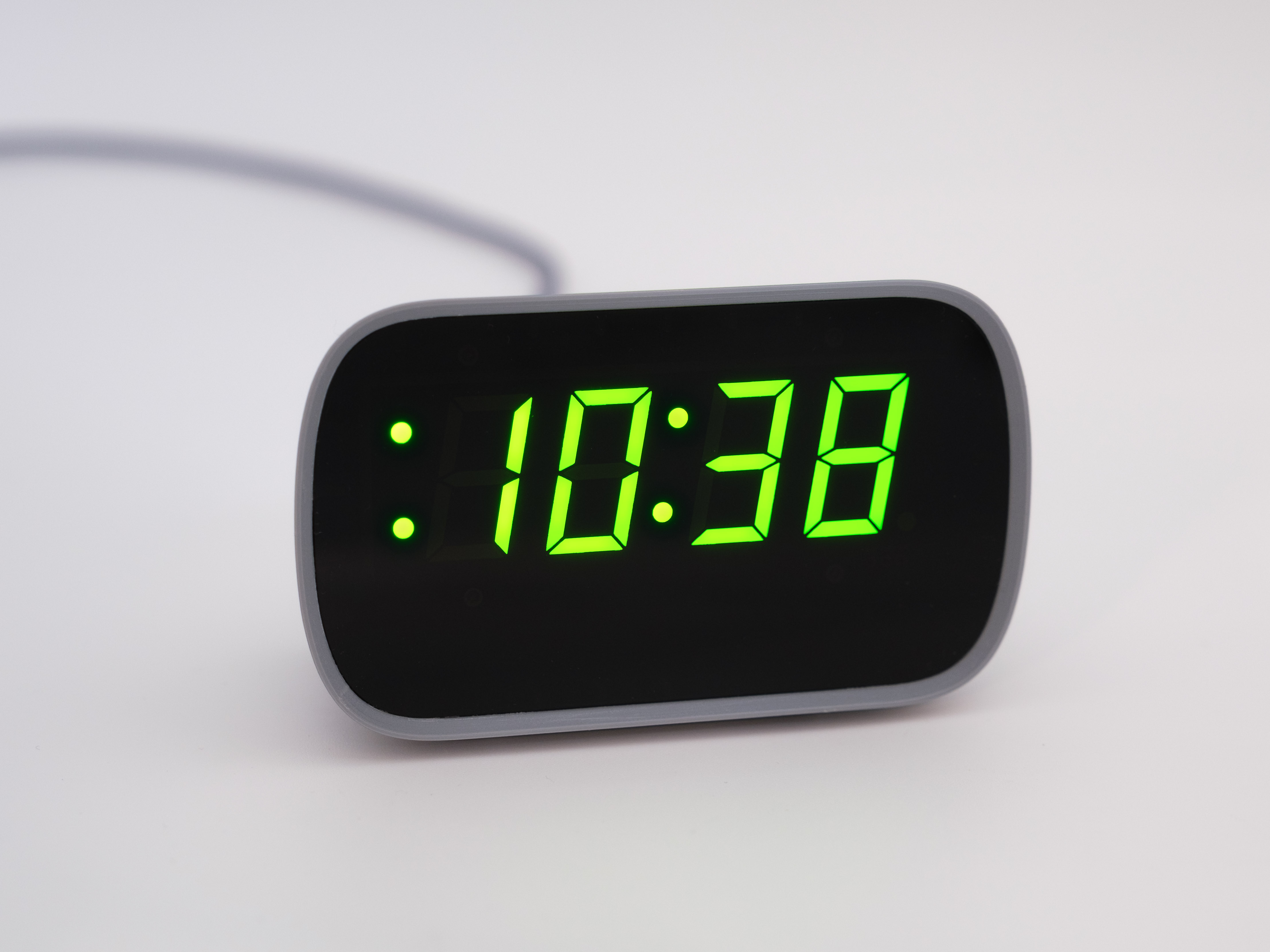
I designed and manufactured my own radio-synchronized bedside clock after growing frustrated with the available off-the-shelf options. I wanted something simple and handsome that would keep perfect time without looking like a science project.
What I ended up designing is a from-scratch clock that synchronizes with the WWVB atomic time broadcast signal from NIST in Colorado. It features a custom enclosure, my own electronics, and firmware written from the ground up. While it was built to solve a personal problem, it turned into a broad exercise in mechanical design, embedded software, PCB layout, RF integration, and even small-batch manufacturing.
Motivation
I began the project with a simple goal, replace my aging bedside clock with something better. Specifically, I wanted something that:
- Had a clear and legible display that was readable without glasses at night
- Looked clean, intentional, and purposeful on my nightstand
- Was always accurate
To my surprise, I couldn’t find any commercial options that met my needs. Most “atomic clocks” on the market were designed for wall mounting. The handful of tabletop clocks that did exist were unattractive, expensive, or cluttered with esoteric features like projecting the time on the ceiling.
So, I decided to build my own.
Time Accuracy
There are a few methods for automatically setting the time on a device. You can:
- Connect it to the internet
- Give it a GPS antenna
- Synchronize with WWVB
The thought of adding another internet connected device to my home was unappealing to me. It would mean managing wifi credentials and device security. These are things I’m not an expert on, especially when there are other equally good options available. I also had concerns that my nightstand, which is not immediately next to a window, would get poor GPS reception. Because of these considerations, I decided to explore the radio synchronization method.
Proof of Concept
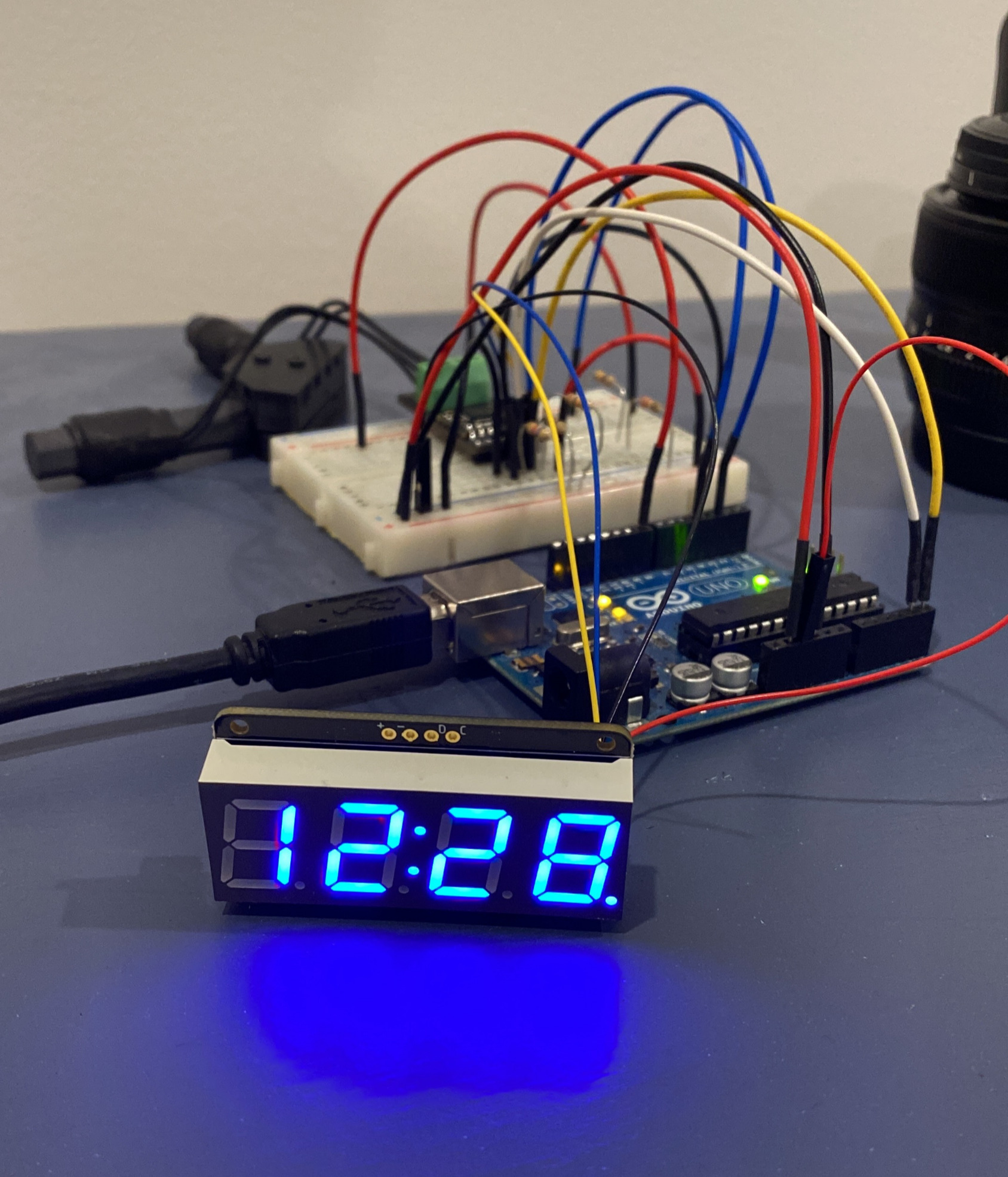
I began by breadboarding a basic proof of concept. I used the ES100-mod WWVB receiver module, connected to an Arduino and a Holtek HT16K33 display driver. My first step was using the provided example code to receive and display the time on a quad-digit, 7-segment LED module.
After proving out the basic idea, I identified and incorporated a larger format display with dedicated AM/PM and alarm indicator LEDs. This would be the only display, so the alarm indicators were reinterpreted as cues to the time sync status.
Industrial Design
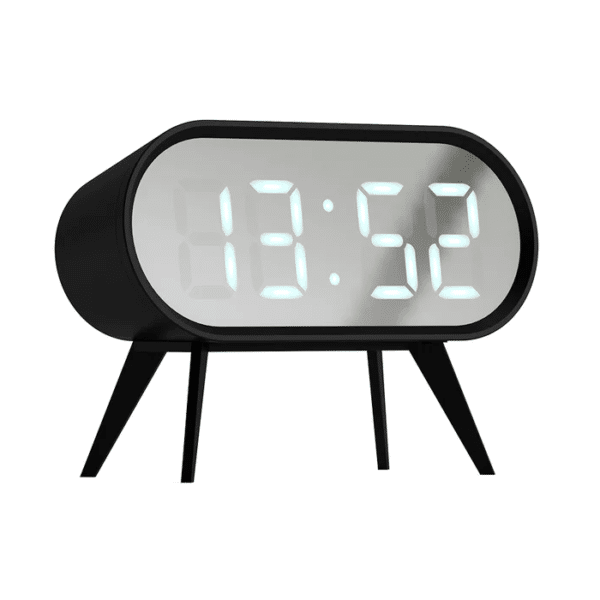
My early concepts were inspired by modernist and mid-century table clocks. I find their clean shapes, subtle curves, and minimal interactions quite appealing. I built a mood board to guide the aesthetic direction and even asked AI to help me with inspiration (this sentence has aged poorly).
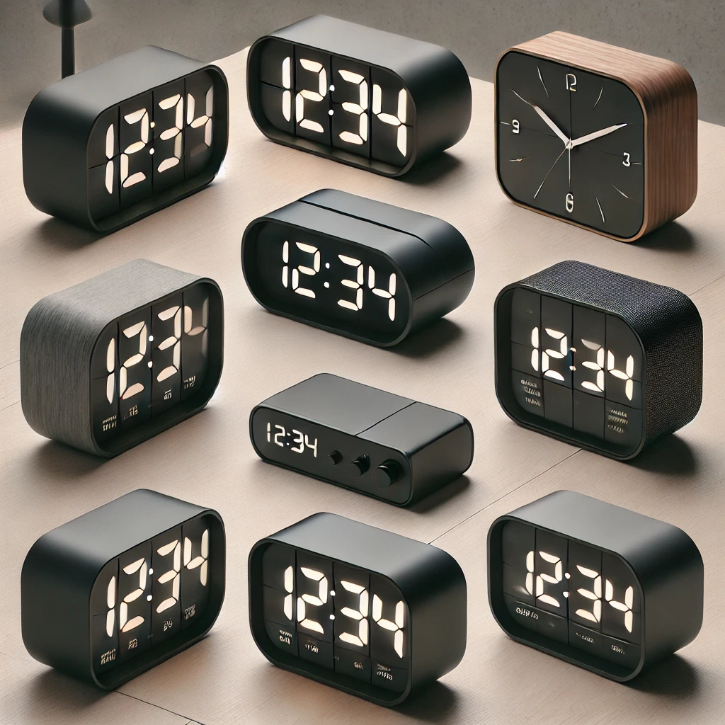
I eventually landed on a design direction I liked and started to build out a 3D model in SolidWorks. Although I planned and did 3D print the housing, I designed it as if it would be injection molded. This means ensuring uniform wall thickness, consideration for draft angles, and planning for parting lines. I prioritized curvature continuity using splines, and validated the surface quality using zebra stripes. The final design features a shallow curved bezel that smoothly transitions to a more rectangular rear panel that houses the buttons.
A downside of using a radio time signal is the clock only knows what time it is, unlike GPS that also knows where it is. This means that you need a way to input your current timezone as well as if you follow daylight savings time rules (looking at you Arizona). Therefore this design has 4 total inputs: Time Zone, DST, as well as an Hour and Minute adjust for getting the time right before a synchronization happens. More on that later.
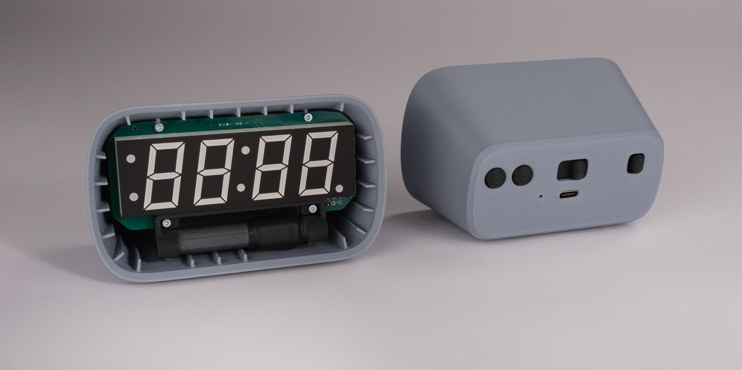
Internally, the layout required careful planning to make efficient use of space. The final configuration split the electronics across two PCBs: a front-facing board for the display, WWVB receiver, and main microcontroller. Then a rear board for the user controls and a very modern USB-C connector. Between the two would be the chapstick-sized 60khz ferrite antenna.
Firmware
Everything was written in C++ and structured around a central timekeeping task. Initially, I made the mistake of storing local time and modifying the clock state directly for daylight saving time and time zone offsets. This ended up being a terrible way to keep track of time and led to inconsistent states or repeat DST transitions.
In the final design, the system maintains UTC as its internal clock reference. Local time is calculated and displayed dynamically after evaluating the state of the rear switches and the DST bits that are broadcast as part of the WWVB signal.
It was a huge accomplishment to watch the DST transition happen in real time and correctly this past March (yes, I stayed up for it).
One interesting quirk of WWVB: it’s a 60 kHz longwave signal and propagates best at night, especially here on the East Coast. You can blame the ionosphere. This means a good time sync really only happens during “dark path” hours. A pair of Hour and Minute adjust buttons allow the time to be set at power up and before a good time sync takes place.
PCB Design
This was my first ever PCB design and I used KiCad to create the schematic and board layout. I designed the board to accept a small-format Arduino (an Adafruit Itsy Bitsy) and included the following:
- HT16K33 LED driver
- Bidirectional 5V to 3.3V level shifting for the ES100 module
- Some basic filtering to hopefully keep the supply voltage free from 60Hz harmonics
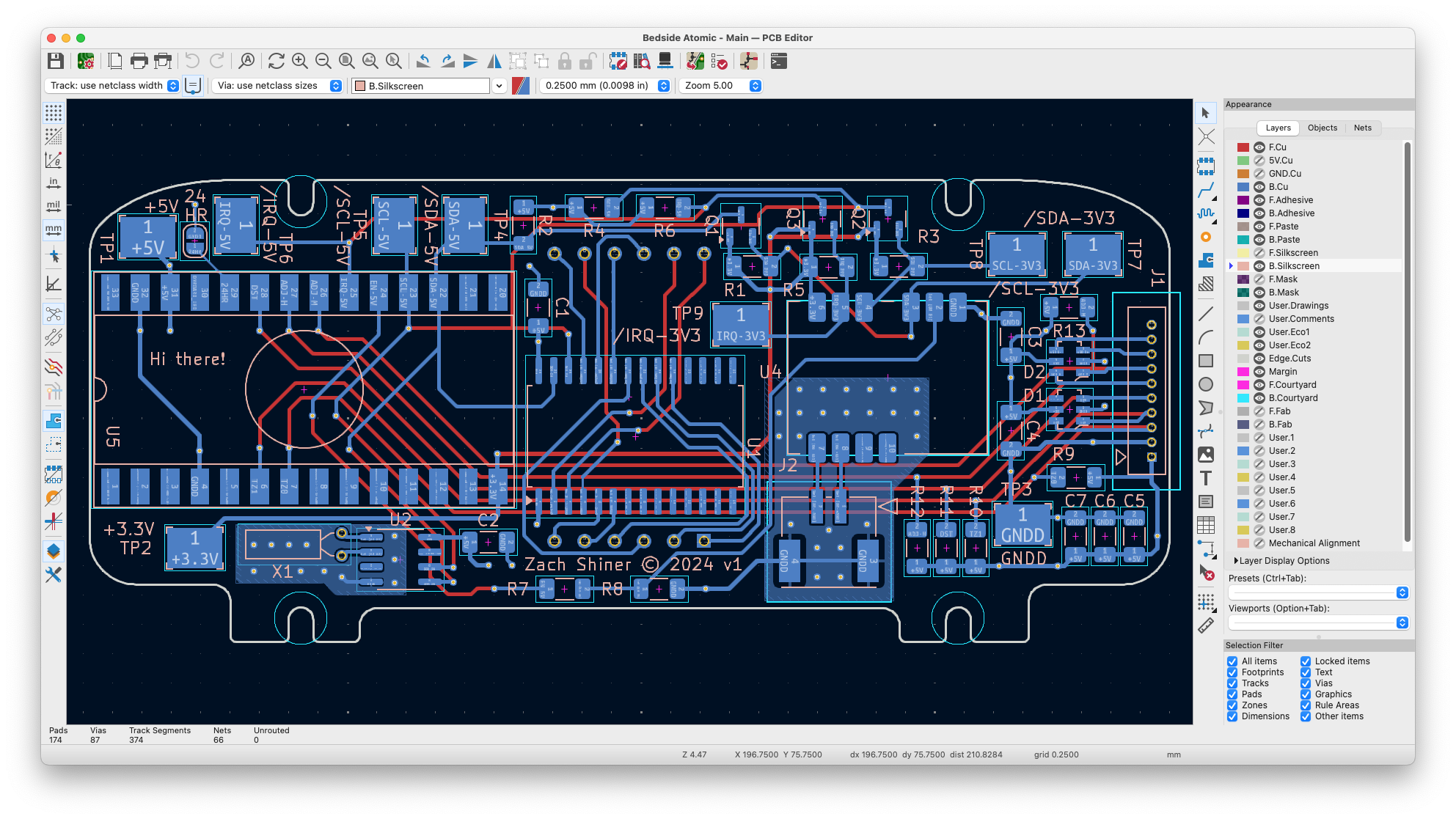
A little design trick that I am proud of is using a pair of diodes to form a 4-2 encoder. This let me read the 4 position Time Zone slider switch with just two signal lines.
With reasonable confidence in my design, and a nod of approval from an Electrical Engineering buddy of mine, I ordered PCBs from the internet and patiently awaited their arrival.
First Testing
Once my boards arrived I set off to assemble them. Doing SMD assembly was another “first” for this project and I rapidly learned that this is not something I enjoy. Nonetheless I am extremely happy with how the assembly turned out.
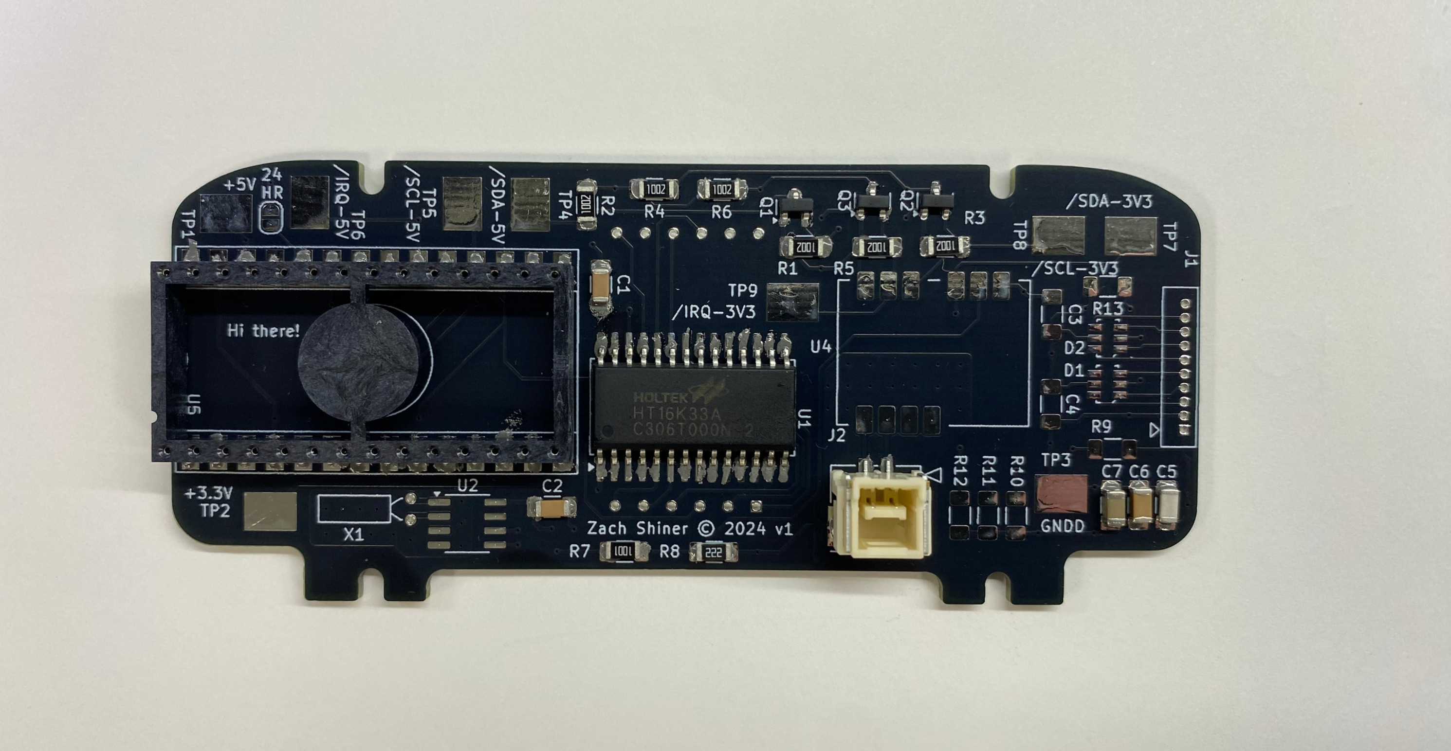
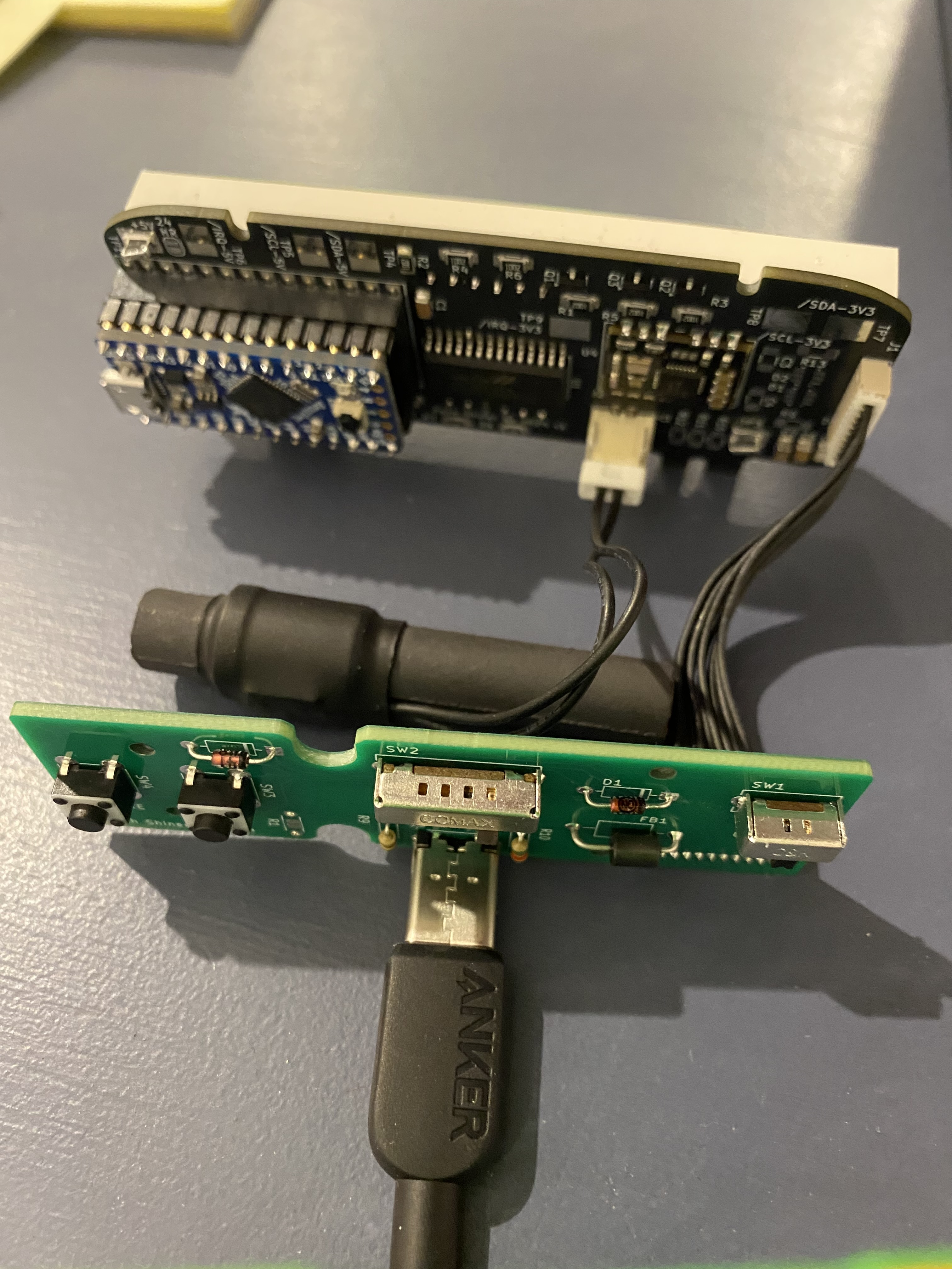
I did a thorough round of testing of this prototype board on the bench. Reception was great, timekeeping was accurate, all the buttons worked as they should and the supply voltage filtering seemed to be effective.
That is until I assembled the clock inside the housing. 😤
While the system functioned reliably on the bench, reception failed entirely once the antenna was enclosed in the 3D printed housing.
This kicked off a long debugging process. I considered whether the 3D printed plastic (possibly containing carbon black pigment) was shielding the signal, whether the PCB ground plane blocked reception, or whether cable routing introduced interference. I even tried wrapping the board in foil.
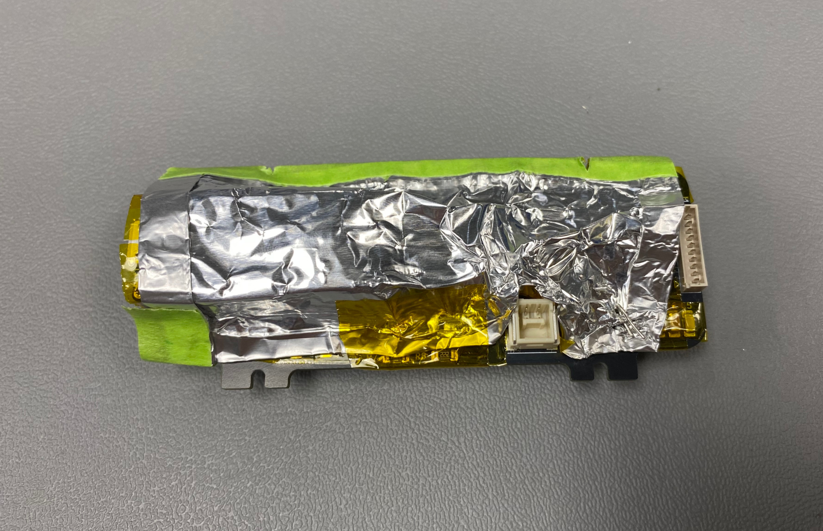
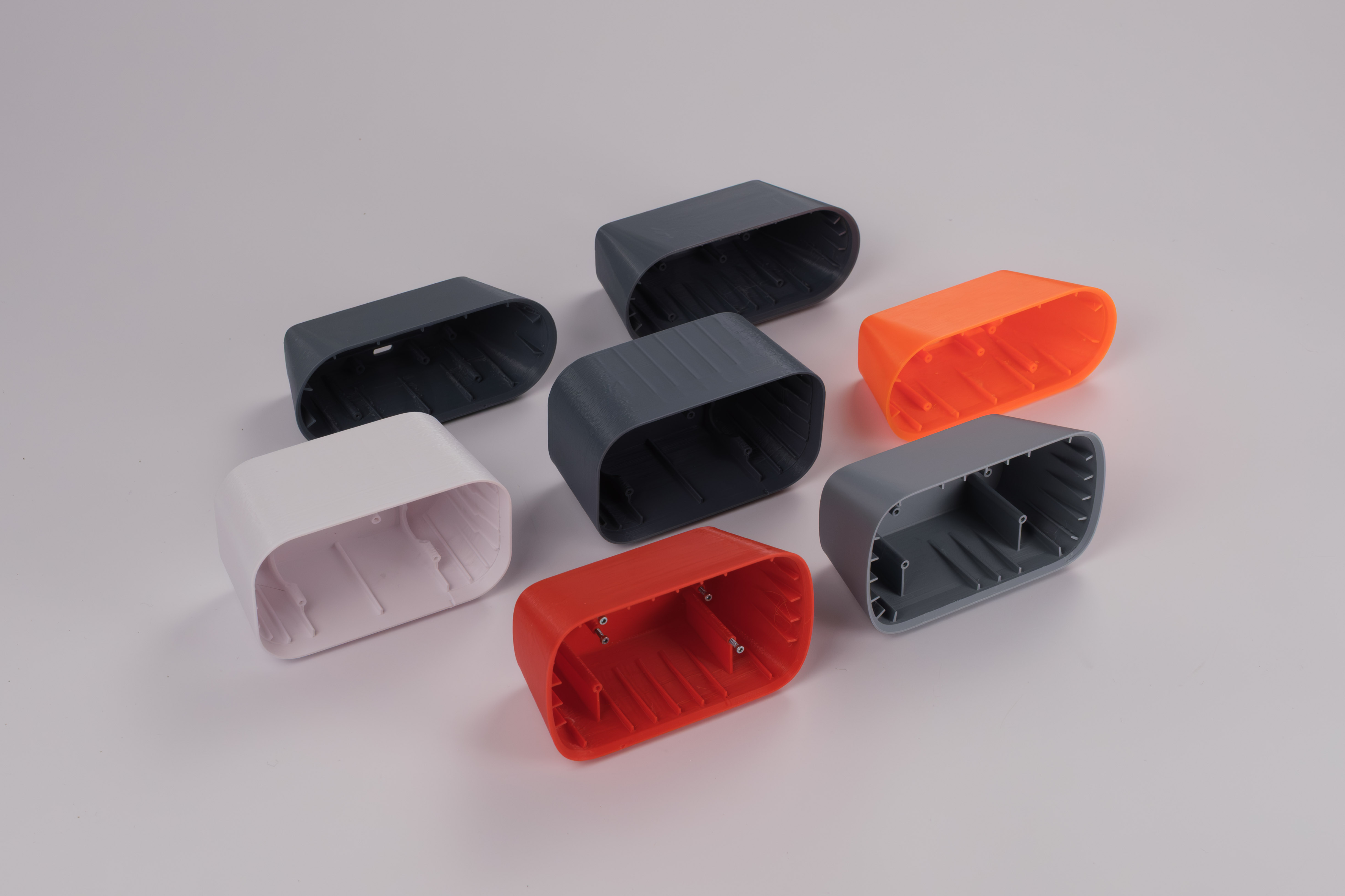
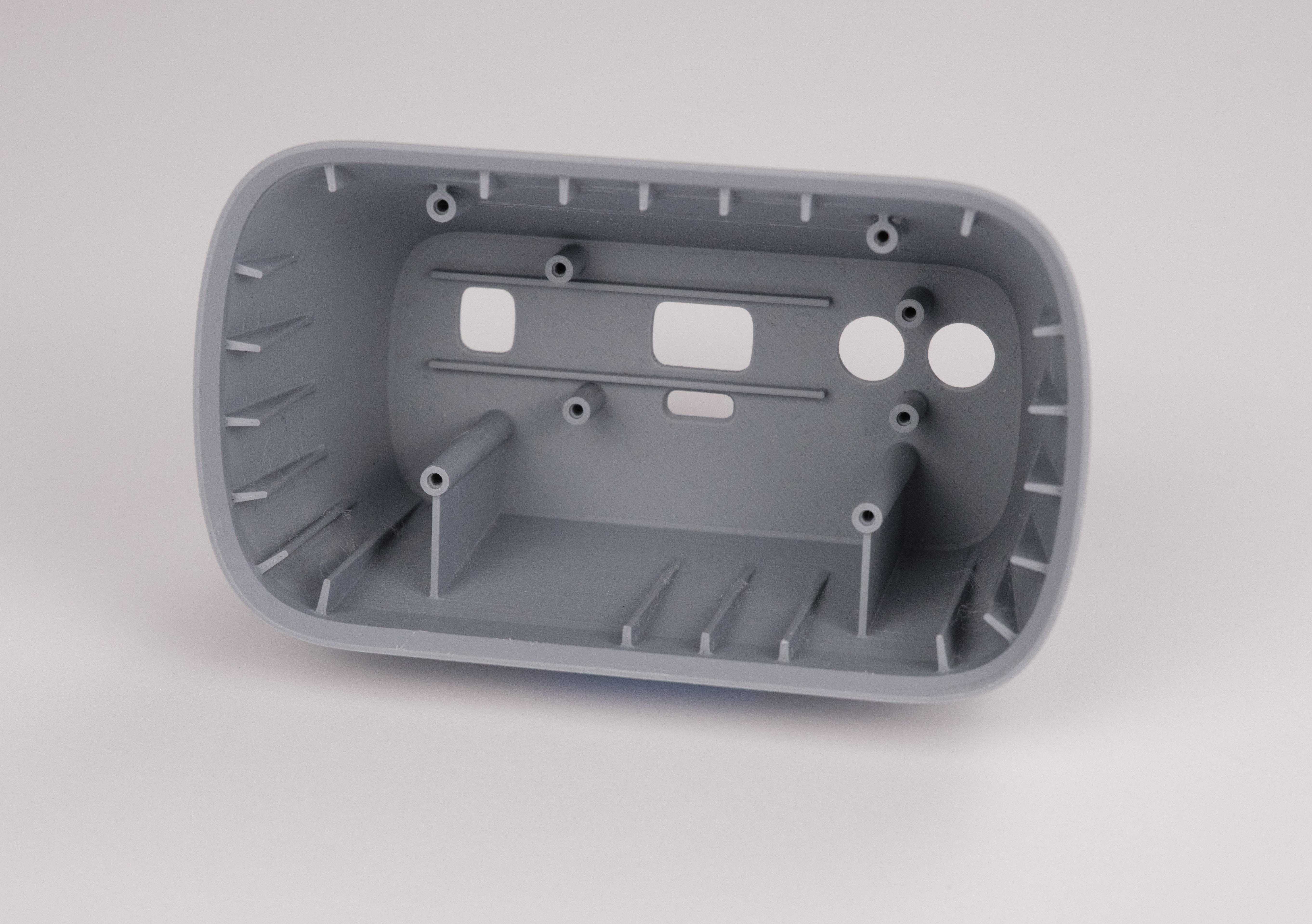
The root cause turned out to be antenna placement. Moving the antenna physically further from the microcontroller seemed to solve the problem. This insight forced a redesign of the enclosure to accommodate the new antenna position. I experimented with a few different layouts and variations on the industrial design until I arrived at something acceptable. The final result was a cleaner, more visually balanced layout that I’m ultimately very pleased with.
This final enclosure was 3D printed from matte gray PLA, and I laser-cut a smoked acrylic lens (#2074) to diffuse the display. This specific material has ~36% light transmittance which is sufficient to hide the digits when off, but fully readable when backlit.
The result looked and felt like a real product. It’s been on my nightstand for months now, and it’s worked flawlessly.
Version 2: Chip-Down Redesign
Once I had a solid V1, I couldn’t resist starting on version 2. The enclosure remained essentially the same, but I wanted to push the electronics further. Specifically, I wanted to design a board that directly integrated a microcontroller, what Brett my advisor call a “chip down” approach, rather than relying on a commercial Arduino board.
For this V2 I made the following changes:
- Directly integrated ATmega32U4 and supporting circuitry
- USB 2.0 support on the rear housing connector (instead of just power)
- Piezo buzzer for UI feedback
- 12/24 hour toggle button
- Future support for dual antennas
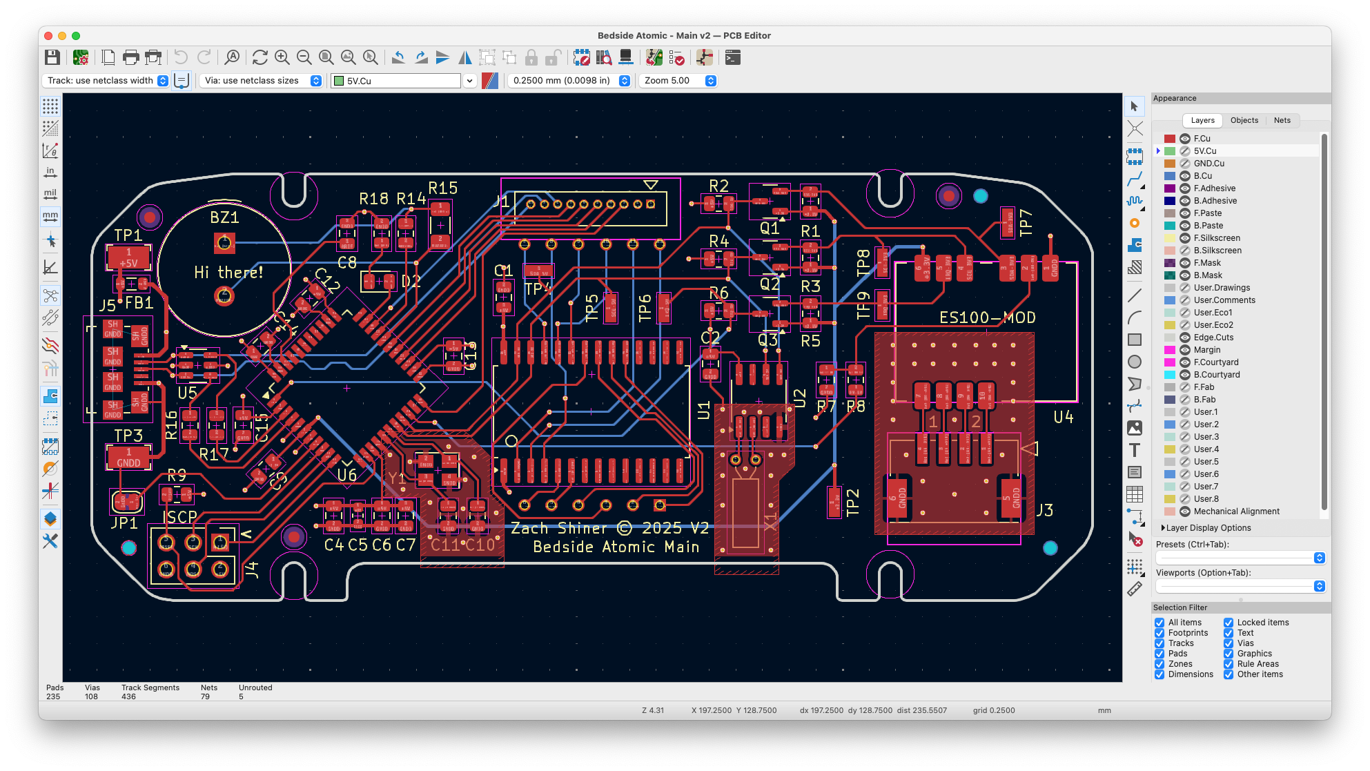
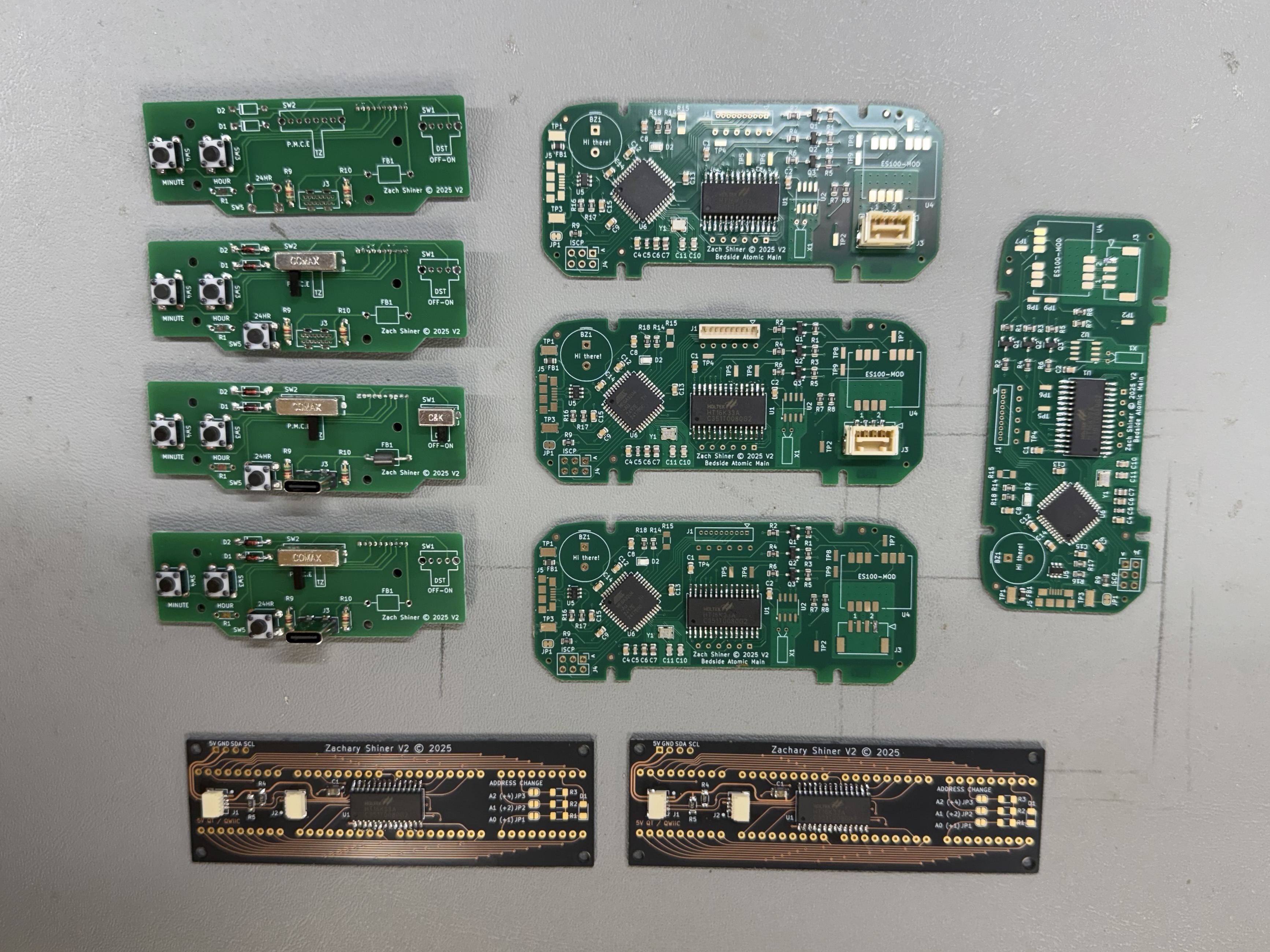
This was also the first time I had a board assembled professionally. After hand soldering my first design, I realized how time consuming surface mount assembly is. This time I used a contract manufacturer to assemble the boards.
I did make one small mistake. I’m using the Arduino Leonardo bootloader on this board and I accidentally wired two signals into the pins that would otherwise drive the board’s TX/RX LEDs. I decided not to modify the bootloader and instead added a few bodge wires to the board to move those signals to unused pins.
Final Thoughts
This project has been deeply rewarding for me. It pushed my skills across hardware, firmware, and product design. It ultimately yielded a result that I use every single day.
I’m already thinking about V3. Battery backup? RGB LEDs? Who knows!
References
- I’ve got my code posted here https://github.com/zcshiner/Bedside_Atom
- I’m using Universal Solder’s ES100-MOD WWVB Receiver
- WWVB Radio Controlled Clocks: Recommended Practices for Manufacturers and Consumers
I might consider selling a board and housing kit if there’s interest. Drop me a line if that’s something you would like.